Angled blade plate
1. General considerations
Introduction
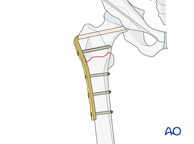
The 95° angled blade plate may be used to stabilize proximal femoral fractures. It is particularly useful when there is a previous deformity, malunion, or nonunion.
Correction of a varus deformity is often required.
The blade is difficult to insert as it has to be correctly orientated in three planes. Precise preoperative planning is always required.
The success of the surgery depends on the position of the implant and the degree of stability achieved.
Preoperative planning
In the proximal femur, the blade needs to be inserted in the middle of the femoral neck and at a predetermined angle to the shaft axis. In addition, the plate portion of the angled blade plate must line up with the axis of the femoral shaft at the end of the procedure.
Because of these technical complexities, a preoperative plan and tactic are essential so that the operation can be conducted step by step. The surgeon must be precise and pay particular attention to anatomical landmarks, the sitting and orientation of the angled blade plate, in both AP and lateral views, as well as rotation of the blade about its axis (which determines the alignment of the plate with the femoral shaft).
Closed vs open reduction
The approach used for implant insertion is giving access to the fracture laterally and allows for open reduction.
Therefore, besides restoration of length, no attempts for closed or percutaneous reduction need to be done.
Implant selection and preoperative planning
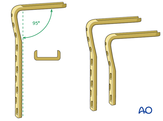
The angled blade plate is a single piece – a fixed-angle device with a U-shaped blade and side plate secured with 4.5 mm cortical screws.
There are a variety of blade and plate lengths available. Usually, a plate with 3–5 holes below the fracture and 2–3 cortical screws provides enough stability.
The length of the blade is determined intraoperatively.
A seating chisel is used to prepare the exact placement of the blade in the femoral neck.
2. Patient preparation and approach
Patient positioning
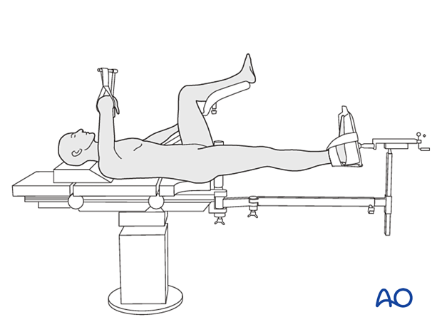
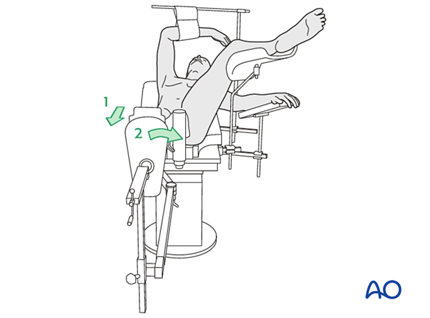
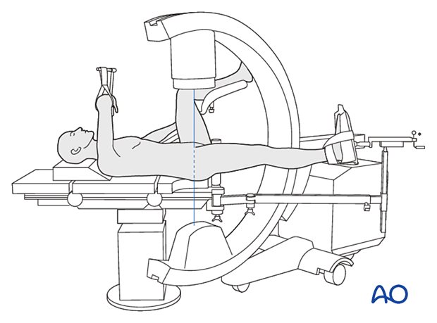
Position the patient supine on a fracture table either with the contralateral uninjured leg placed on a leg holder or in a scissors configuration.
In fresh cases, a traction table might not be necessary, and the procedure can be done with the patient positioned on a radiolucent table designed for use with image intensification. In this case, traction can be applied by an assistant.
For C-arm positioning to acquire optimal AP, lateral, and axial views, read the additional material on:
Approach
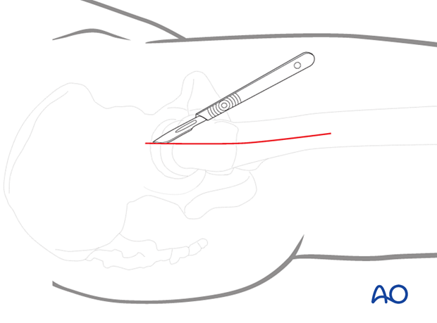
Usually, a limited open reduction through a lateral approach is sufficient for both implant insertion and reduction.
Enlarge the lateral incision as necessary by increasing its length and retracting the vastus lateralis anteriorly and medially.
3. Reduction
Preliminary reduction
Preliminary reduction to restore length and rotation is usually achieved by:
- Pulling in the direction of the long axis of the leg to distract the fragments and regain length
- Slight abduction to relax the abductors
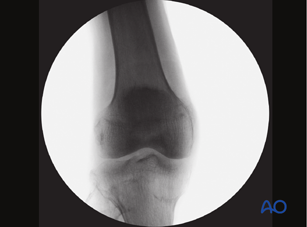
- Adjustment of internal rotation of the femoral shaft ...
... until the patella is facing forward on an AP view of the knee joint
Reduction with forceps
Clear the fracture site of interposed soft tissue all along the fracture line as needed.
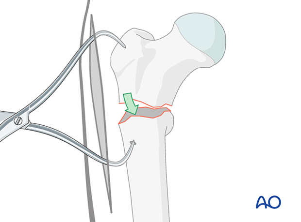
Align the corresponding fracture surfaces, so they are opposite one another. Then place a pointed reduction forceps strategically (ie, so that it does not interfere with later plate positioning). Reduction is achieved by closing the forceps.
Often the bone of the shaft is too hard to get a good hold for the forceps tip. In this case, drill an anchor hole with a 3.2 mm drill.
Confirm the reduction with the image intensifier.
Hold the reduction throughout the procedure (the forceps are not shown for clarity of illustrations).
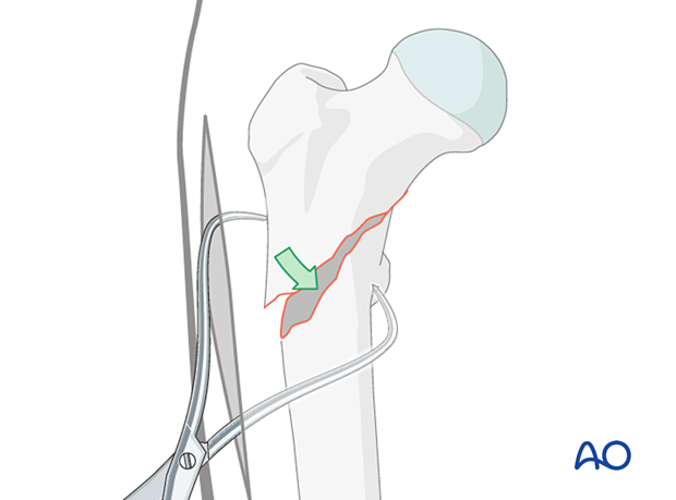
In a reverse oblique fracture, place pointed reduction forceps so that one point engages just anterior to the lesser trochanter.
Check the reduction in both the AP and lateral view with an image intensifier.
Assessment of reduction quality
Visually confirm anatomical reduction of the lateral cortex through the incision.
Also, read the fracture lines on the image intensifier views for the medial and posterior cortex.
Identify gaps or increased density due to overlapping of fragments.
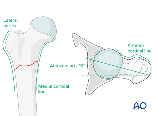
Follow the medial cortical line on the AP view and the anterior cortical line on the axial view. Identify any translational or angular malalignment.
Acceptable reduction quality shows the following patterns:
In the AP view:
- Continuous medial cortical line
- No varus angulation
In the lateral view:
- Anteversion approximately 15°
- Continuous anterior cortical line
For more details, see the additional material on assessment of reduction quality.
4. Preparing the blade channel
Planning for plate insertion
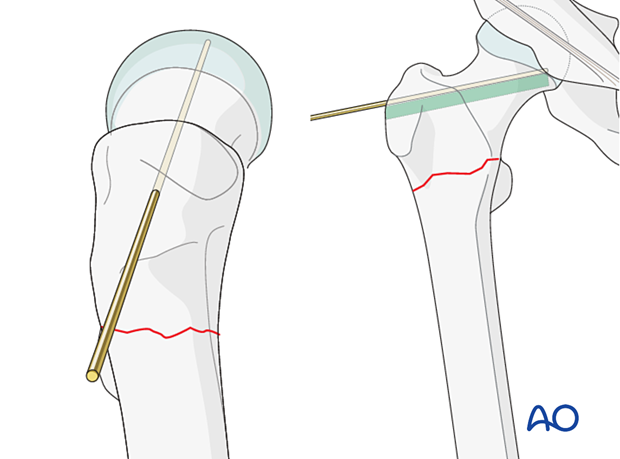
Position the planned plate on the skin with the distal part parallel to the femoral shaft and take an AP view.
Adjust the position in the coronal plane until the blade comes to lie below the tip of the greater trochanter and above the inferior medial cartilage-cortex junction of the head.
The lateral bend of the blade plate should match the trochanteric ridge.
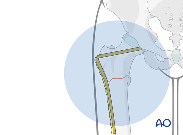
Select a blade plate with a blade long enough, so its tip comes to lie 5–10 mm off the subchondral cortex of the head.
Insertion of the guide wire
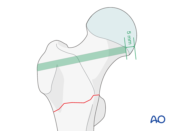
Insert the guide wire parallel and 5 mm superiorly to the planned blade and check its position in AP and lateral views.
Mark the entry site on the lateral aspect of the greater trochanter employing image intensification to confirm the correct entrance location.
Opening the entry site and drilling the blade track
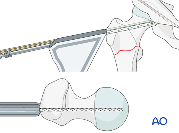
Check the anteversion of the guide wire on a true axial view. On the AP view, make sure the direction of the guide wire is 95° to the shaft to restore the anatomical neck-shaft axis.
Start with drilling the first hole with a 4.5 mm drill parallel to the guide wire through the middle hole of the triple drill guide in an optimal direction as far as the length of the blade.
Check with the guide wire and true axial views.
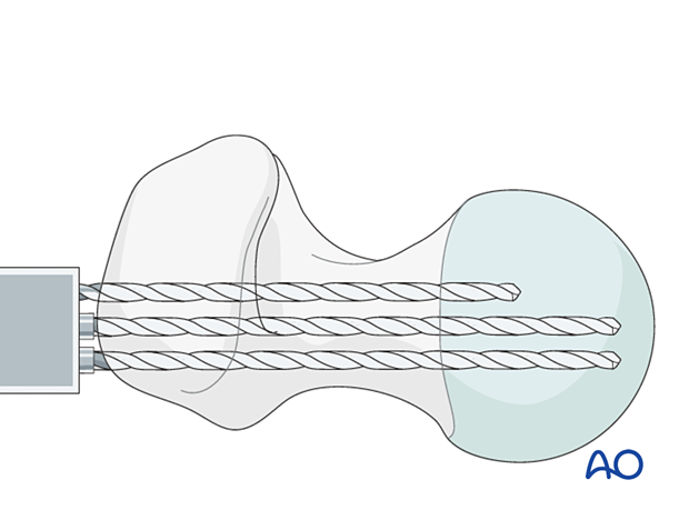
Drill the two other holes with the triple drill guide parallel to the first.
Remove all drills and the drill guide.
At this point, the blade length may be checked with a depth gauge.
Preparing the track for the blade
Link the holes with the router to form a slot.
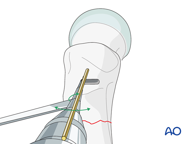
Attach the chisel guide onto the seating chisel. Set the flap right on the axis of the femoral shaft in axial view to avoid sagittal malreduction.
When inserting the chisel, take great care to check the degree of anteversion, rotation, and angle to the femoral shaft. Any inaccuracy will result in plate malpositioning.
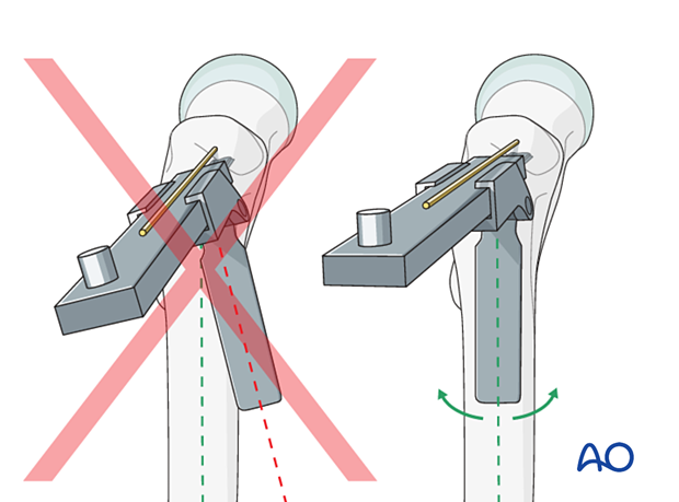
Appropriate technique for controlling rotation while advancing chisel
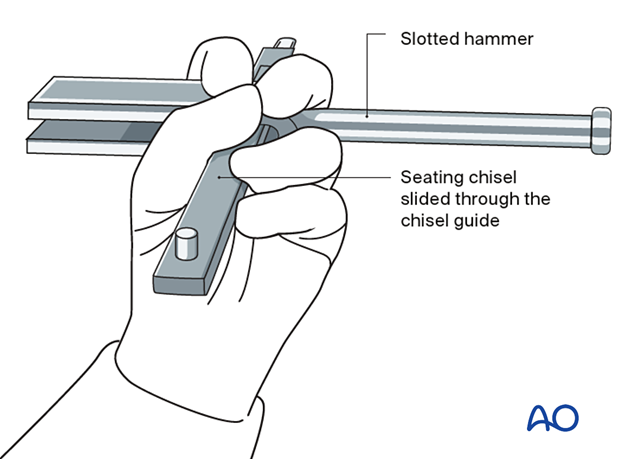
Insert the seating chisel with gentle hammering and intermittent backslapping, under image intensification control in both planes, across the femoral neck into the head until the required depth is reached. During insertion, control the chisel rotation with the slotted hammer.
The required blade length may be read from the scale on the chisel.
5. Plate insertion
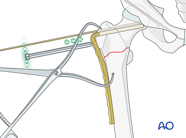
Mount the chosen blade plate correctly onto the inserter: the handle of the inserter and the blade of the plate must be aligned in the same plane (the notched head of the inserter allows for fine adjustment). Tighten the bolt of the insertion handle firmly.
Only when the plate assembly is ready to be employed, exchange the seating chisel for the blade plate.
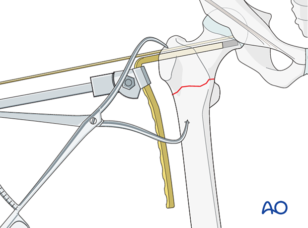
Insert the plate with gentle hammer blows.
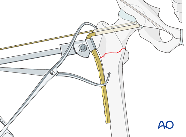
Use the impactor to seat the final plate position.
Remove the guide wire.
6. Plate fixation
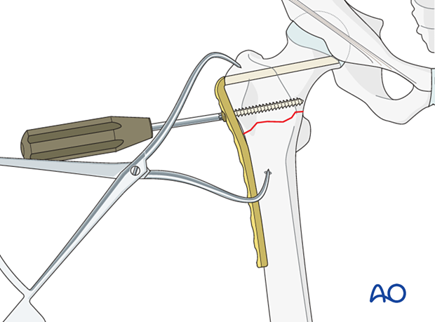
Insertion of proximal screw
Insert a 6.5 mm cancellous bone screw or a 4.5 mm cortical screw bicortically into one of the holes next to the blade.
Compression plating
With transverse fractures, compression can be applied while inserting plate screws in the shaft.
This can be achieved by inserting a first screw (and even a second) in a compression mode.
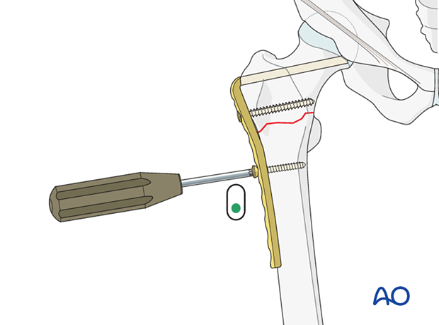
For maximum compression, use an articulated tension device (ATD).
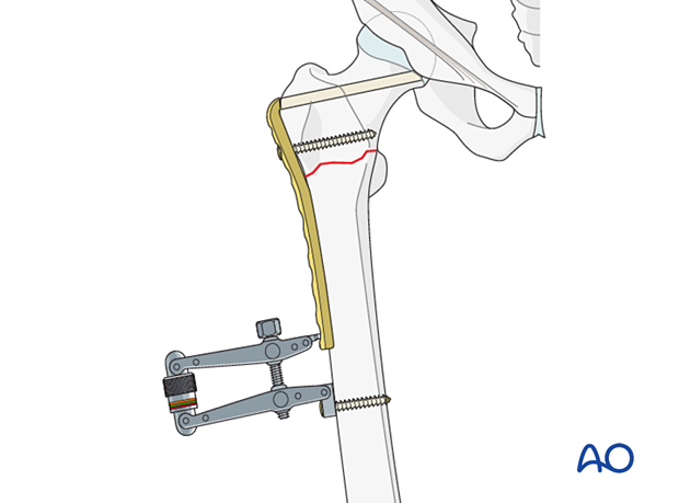
Insert the remaining distal screws in neutral mode.

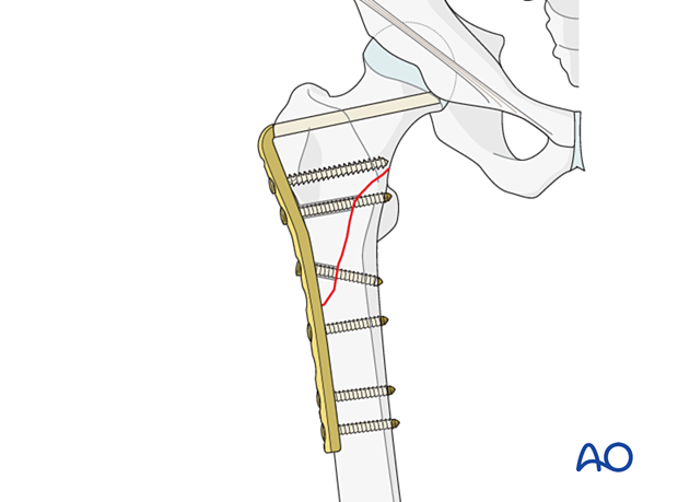
Lag screw through plate
In oblique fractures, compression may lead to shearing and should therefore not be applied.
If the fracture allows, plan for a lag screw through the plate overdrilling the near cortex.
7. Final assessment
Confirm fracture stabilization and implant position on both AP and lateral views.
8. Aftercare
Postoperative mobilization
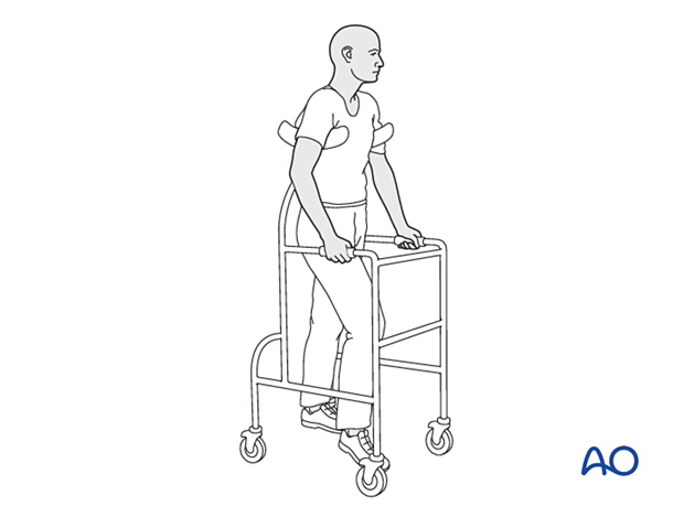
Initial restricted weight bearing is required for the young patient. This can be reassessed at 6 weeks.
Unrestricted range-of-motion exercises of the hip joint are allowed.
Pain control
To facilitate rehabilitation and prevent delirium, it is important to control the postoperative pain properly, eg, with a specific nerve block.
VTE prophylaxis
Patients with lower extremity fractures requiring treatment require deep vein prophylaxis.
The type and duration depend on VTE risk stratification.
Follow-up
Follow-up assessment for wound healing, neurologic status, function, and patient education should occur within 10–14 days.
At 3–6 weeks, check the position of the fracture with appropriate x-rays.
Recheck 6 weeks later for progressive fracture union.
Implant removal
Only if necessary (eg, painful irritation), and not before union of the fracture. There is a high risk of a femoral neck fracture.


