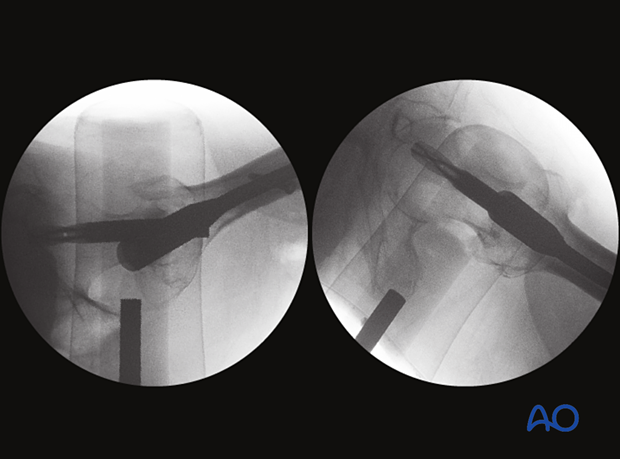
Intraoperative imaging of the proximal femur
1. Introduction
Fluoroscopic visualization of anatomical fracture reduction and correct implant placement for the proximal femur can be significantly facilitated using the following views:
- AP view of the proximal femur
- Axial view of the proximal femur
- Lateral view of the proximal femur
The lateral view does not correctly reflect the implant position in the head-neck fragment. An axial view is therefore necessary.
AO teaching video
AO TV 2022: Interview with editor and authors of the third editionIntraoperative Imaging of the Proximal Femur
Daniel Rikli provides insight on tips and tricks in intraoperative imaging of the proximal femur. (21 minutes)
2. AP view of the proximal femur
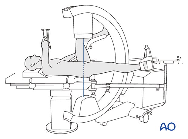
Positioning for optimal view
- The beam is placed perpendicular to the femoral shaft and the coronal plane
- The leg is internally rotated with the patella facing upward
Verification of optimal view
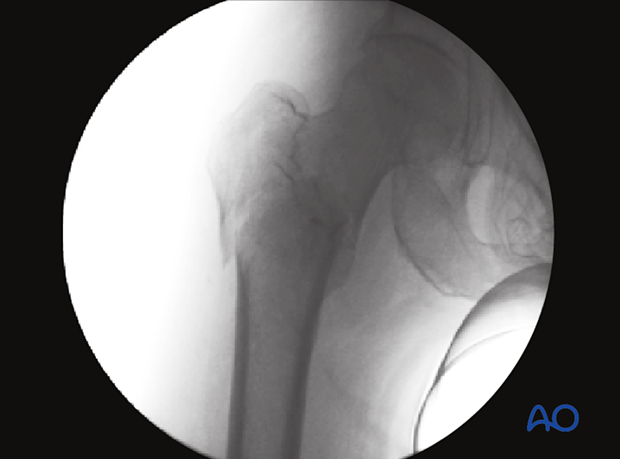
The optimal view is obtained when:
- Trochanteric area is in the center of the screen
- Both the femoral head (including the hip joint) and shaft are visible
Anatomical landmarks and lines
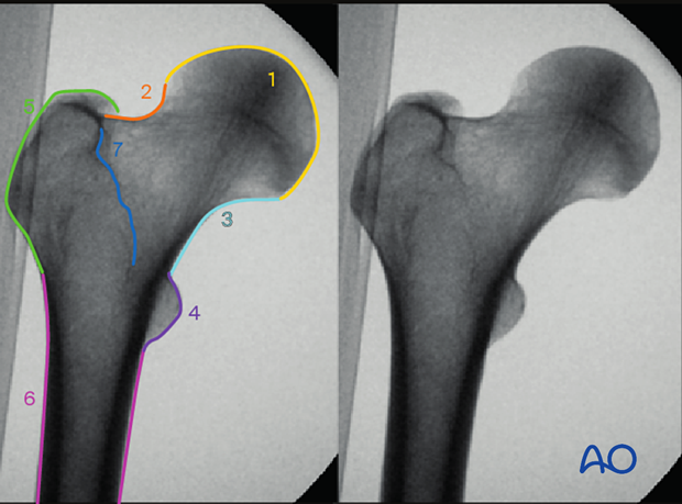
In the AP view of the proximal femur (here with a trochanteric fracture), the following landmarks and lines can be observed:
- Femoral head
- Femoral neck
- Medial line
- Lesser trochanter
- Greater trochanter
- Femoral shaft
- Intertrochanteric line (anterior) superimposed with the intertrochanteric crest (posterior)
What can be observed
- Varus or valgus malalignment
- Rotational malalignment
- Translational displacement
- Correct guide-wire insertion
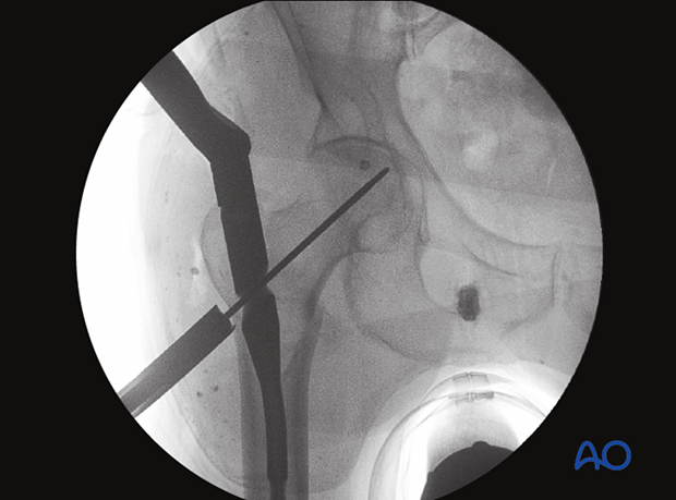
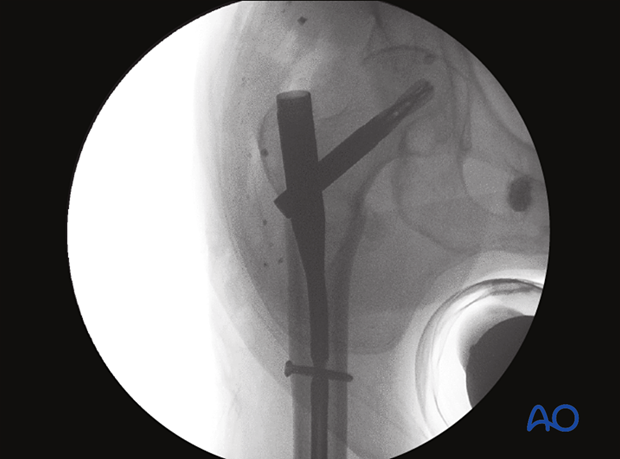
- Correct implant positioning
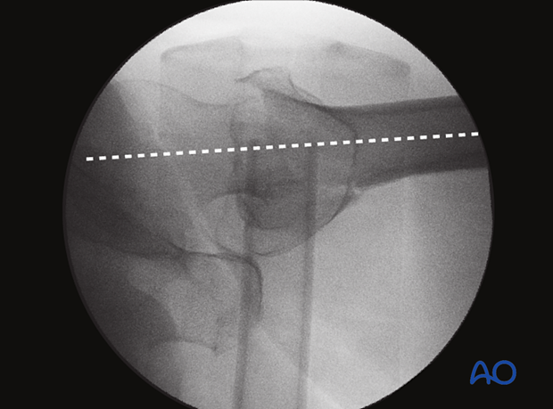
3. Axial view of the proximal femur
Positioning for optimal view
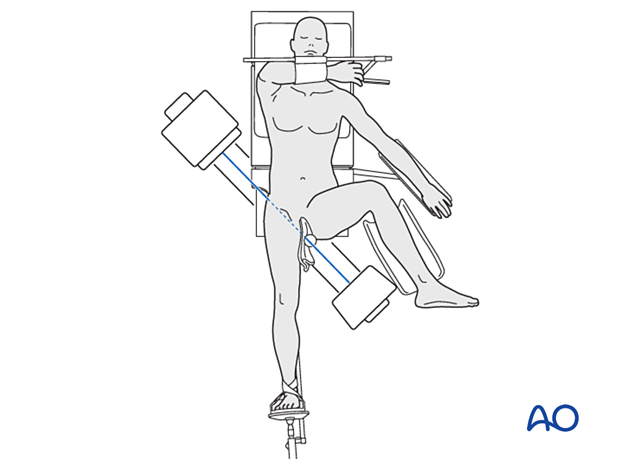
- The beam track should avoid the contralateral hip
- A hemilithotomy position of the patient, scissoring, or abduction of the contralateral leg may be helpful to optimally place the C-arm
- The beam is rotated externally by approximately 15° off the coronal plane
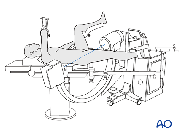
- The beam is positioned 30°–45° to the longitudinal axis of the injured leg
Verification of optimal view
The optimal view is obtained when:
- Centered image showing head, neck, and proximal end of shaft
- Head-neck axis is in line with the femoral shaft (within the range of 170° and 190°)
- Contralateral hip is not obstructing the view
Anatomical landmarks and lines
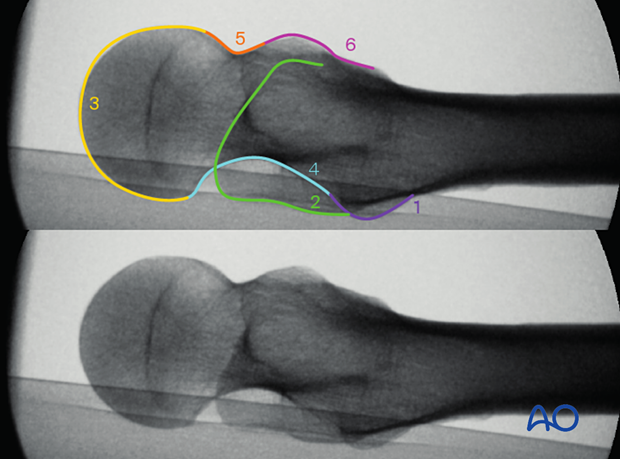
In the axial view of the proximal femur, the following landmarks and lines can be observed:
- Lesser trochanter
- Greater trochanter
- Femoral head
- Posterior line
- Anterior line
- Capsule insertion (intertrochanteric line)
What can be observed
- Quality of reduction
- Head-neck and shaft axis alignment
- Correct guide-wire insertion
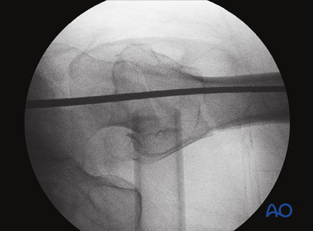
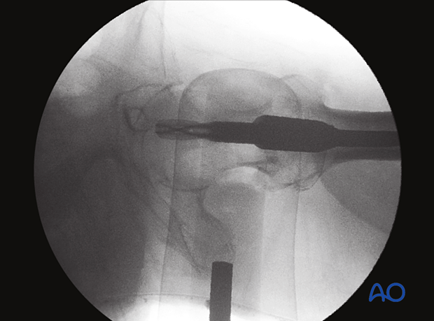
- Acceptable implant positioning (center-center)
4. Lateral view of the proximal femur
The lateral view shows the anteversion of the head and neck.
Positioning for optimal view
- The beam track should avoid the contralateral hip
- A hemilithotomy position of the patient, scissoring, or abduction of the contralateral leg may be helpful to optimally place the C-arm
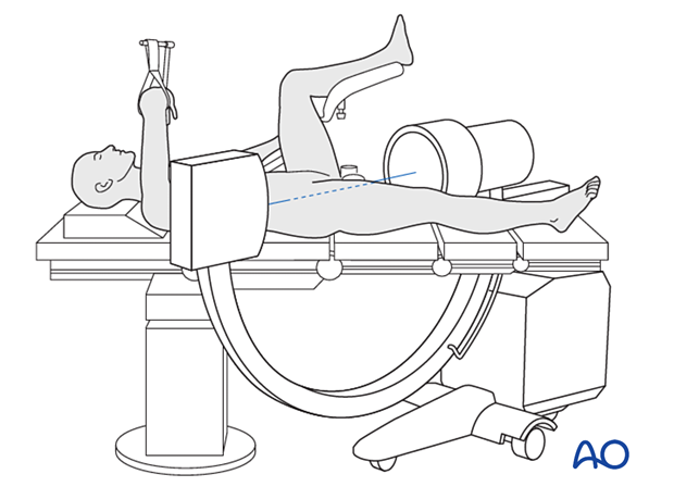
- The beam is positioned horizontally, 30°–45° to the longitudinal axis of the leg and in the coronal plane

Verification of optimal view
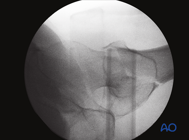
The optimal view is obtained when:
- Centered image showing head, neck, and proximal end of shaft
- Normal anteversion between head-neck axis and femoral shaft is visible
- Trochanteric area is centered in image
- Contralateral hip is not obstructing the view
Anatomical landmarks and lines
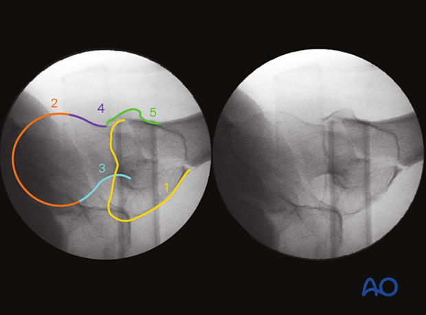
In the lateral view of the proximal femur (here with a trochanteric fracture), the following landmarks and lines can be observed:
- Greater trochanter
- Femoral head
- Posterior line
- Anterior line
- Capsule insertion (part of the intertrochanteric line)
What can be observed
- Quality of reduction
- Anteversion
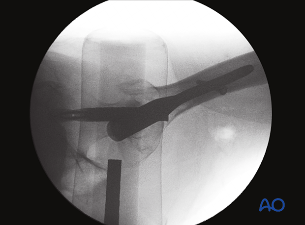
The lateral view is not optimal to confirm implant position (eg, center-center of neck screw/blade).
5. Cases
Case 1
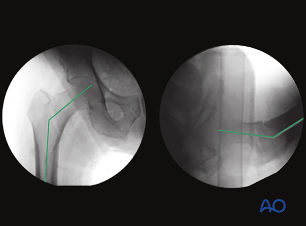
AP and lateral views showing the neck-shaft angle and the anteversion
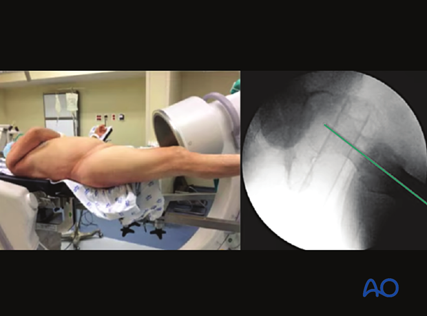
External rotation of the C-arm of approximately 15° from the horizontal (coronal plane) towards the AP view results in an axial view.
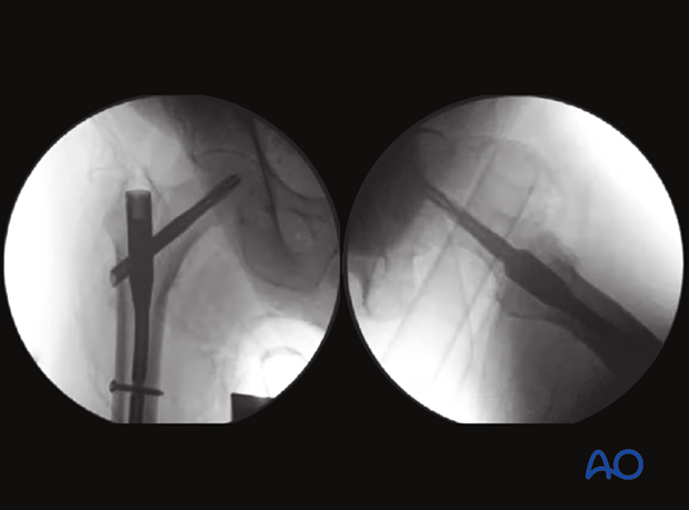
AP and axial views are used to confirm center-center position of the blade in the femoral head-neck axis after nail fixation.
Note that these correct views can only be obtained with acceptable reduction of the fracture.
Case 2
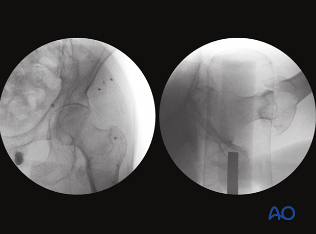
This case of a pertrochanteric fracture is fixed with intramedullary nailing.
The AP and lateral views are used to confirm reduction.
Correct guide-wire insertion through the tip of the greater trochanter is confirmed on the AP view.
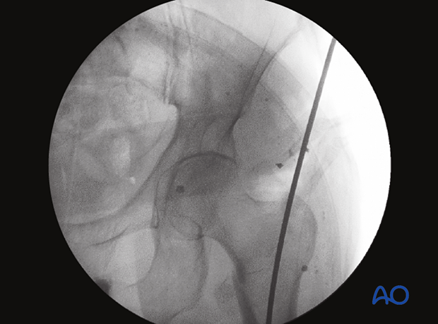
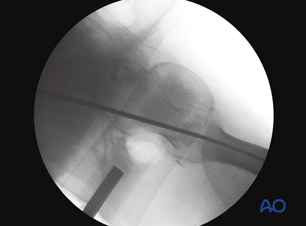
The axial view confirms correct placement of the guide wire through the greater trochanter into the medullary canal of the femoral shaft.
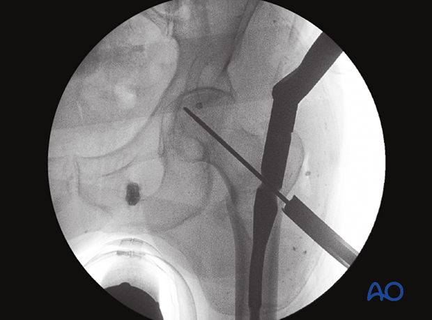
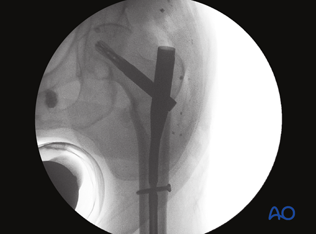
This AP view confirms correct guide-wire insertion for the helical blade (center of the head).
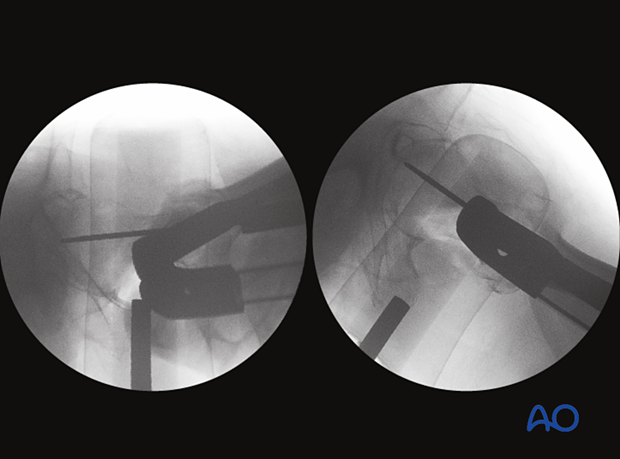
Only the axial view (right image) gives reliable information of the guide-wire position in the head-neck fragment (center of the head).
AP view to confirm correct implant position
Lateral and axial view of the same case
