Patient examination: radiological evaluation (XR, CT, MRI)
1. Preliminary remarks
Radiological evaluation of an injured spine includes plain radiographs, Computerized tomography (CT) and Magnetic Resonance Imaging (MRI) scans. The purpose of radiological evaluation is to:
- identify the location and extent of injury
- determine features of vertebral instability
- assess the severity of neurological compression and injury
- classify injury patterns
- identify multilevel injuries
2. Plain radiographs
Introduction
Good quality plain radiographs in two planes (antero-posterior and lateral) must be performed in all patients with suspected spinal trauma.
The appropriate radiograph is performed based on local tenderness or deformity and the presence of neurology (in case of neurological injury).
For the upper cervical spine one can use a C2 targeted x-ray examination.
The AP view is recorded through the open mouth.
Lateral includes occiput to C3.
If the radiographs are not satisfactory or are inconclusive, a CT scan must be performed.
What is seen in the AP radiograph
Anatomical landmarks seen in the AP view:
- Odontoid
- C2 body
- C1–C2 facet joint
- C1 lateral mass
- Occ–C1 joint
- Occiput
- Bifid spinal process
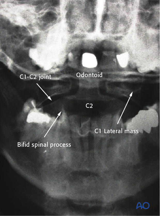
What is seen in this image:
- Lateral dislocation of the lateral mass of C1 (Positive Spence sign if dislocation exceeds 7mm)
What this indicates:
- C1 fracture
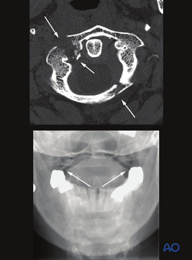
What is seen in this image:
- Fracture line of the odontoid
- Fracture lines of the odontoid are not usually easily seen in the AP view
What this indicates:
- Type II or III fracture
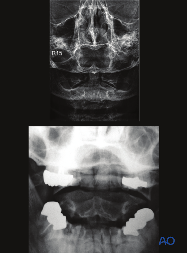
What is seen in the lateral radiograph
Anatomical landmarks seen in the lateral view:
- Occiput
- Anterior and posterior arch of C1
- Odontoid
- C2 body
- Isthmus and lamina of C2
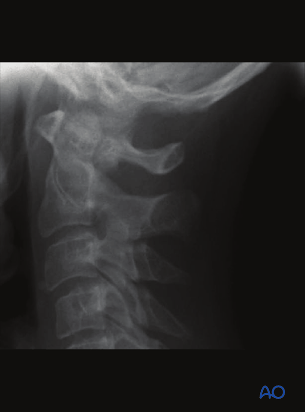
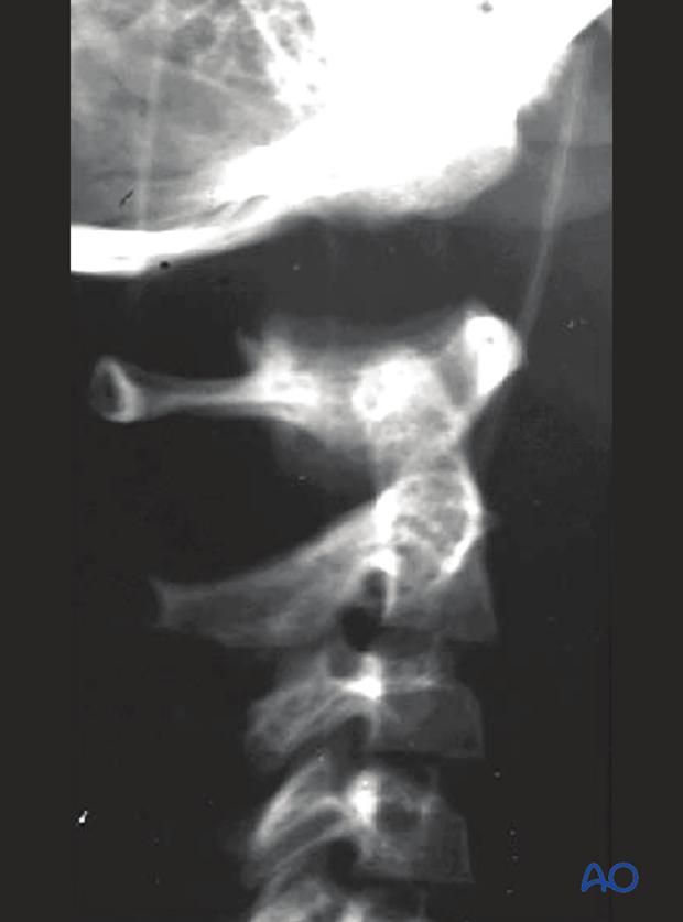
What is seen in this image:
- Large atlanto-occipital distance
What this indicates:
- Axial atlanto-occipital dislocation
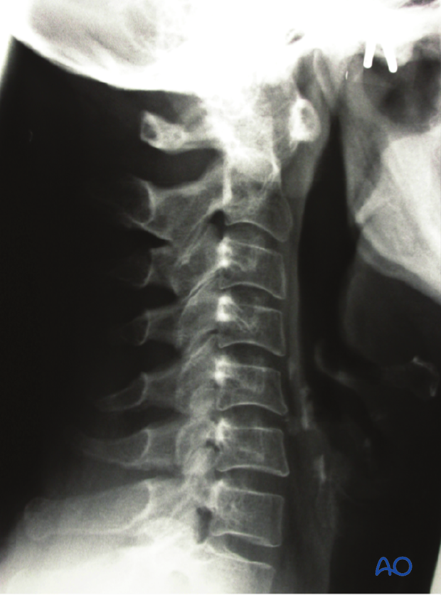
What is seen in this image:
- Increased atlanto-axial distance
What this indicates:
- Atlanto-axial instabillity
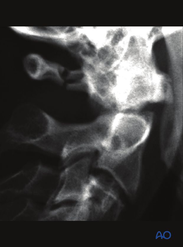
What is seen in this image:
- Fracture of the posterior arch of C1
What this indicates:
- Fracture of C1
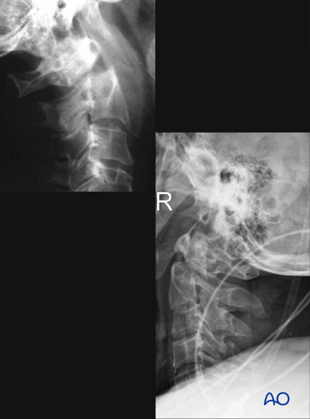
What is seen in this image:
- Lefthand image shows fracture of the neck of the odontoid with extension
- Righthand image shows fracture of the neck of the odontoid with posterior dislocation
What this indicates:
- C2 odontoid fracture
What is seen in this image:
- Fracture of the pars interarticularis of C2 and slight anterior slippage of C2 body
What this indicates:
- Traumatic spondylolisthesis of C2
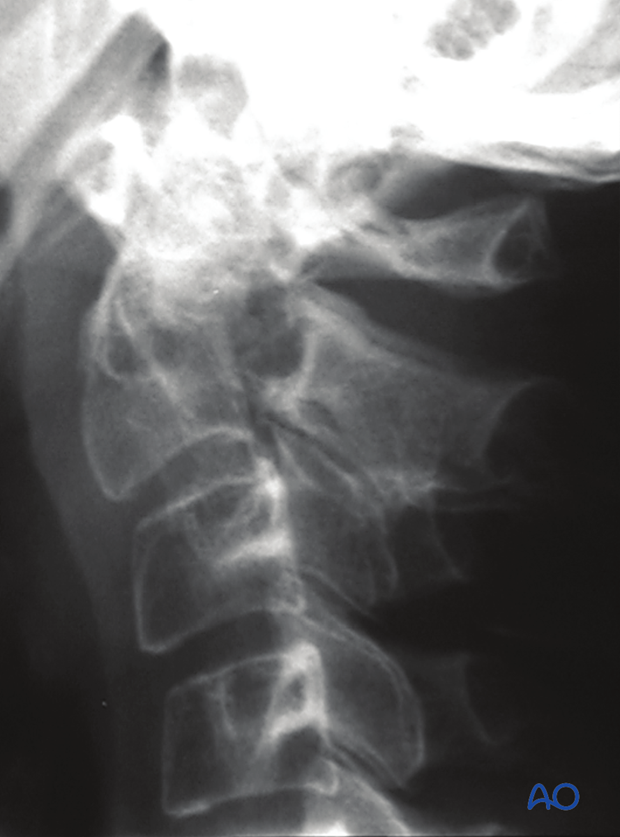
What is seen in this image
- Anterior slippage of the C2 body
What it indicates
- Unstable traumatic spondylolisthesis
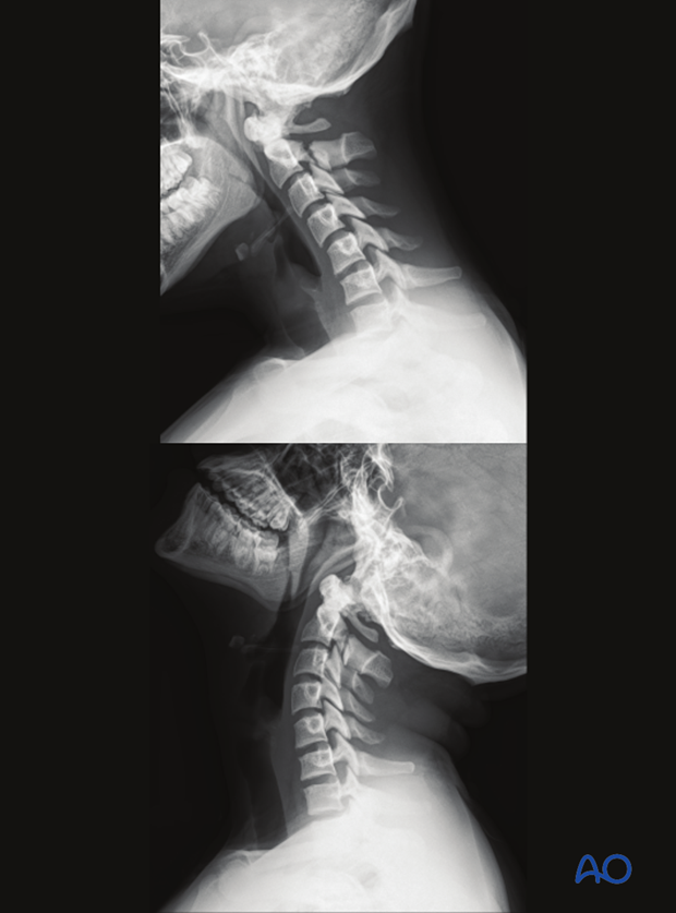
3. What is seen in CT scans
CT can reveal associated injuries as well as rule out suspected fractures which are not present.
What is seen:
- Precise fracture morphology
- Associated injuries
- Extent of vertebral body comminution and displacement
Which view:
- Sagittal, axial, and coronal
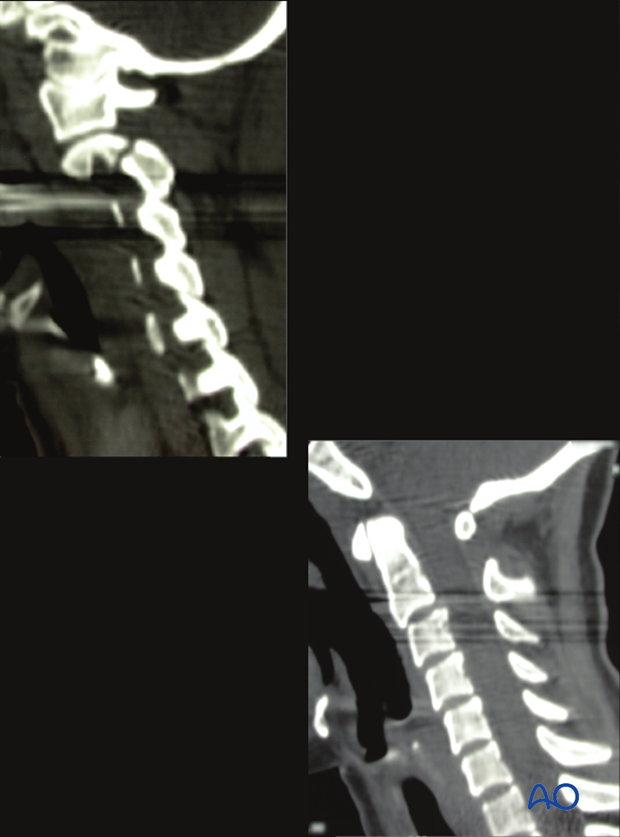
What is seen in this image:
- Fracture of the pars and angulation C2–C3
Which view:
- Lateral
What this indicates:
- Fracture of the pars
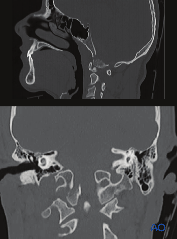
What is seen in this image:
- Occipital condyle fracture
Which view:
- Lateral, coronal
What this indicates:
- Fracture of occipital condyle
What is seen in this image:
- C1 atlas fracture
Which view:
- Coronal, axial
What this indicates:
- Fracture of the C1 ring
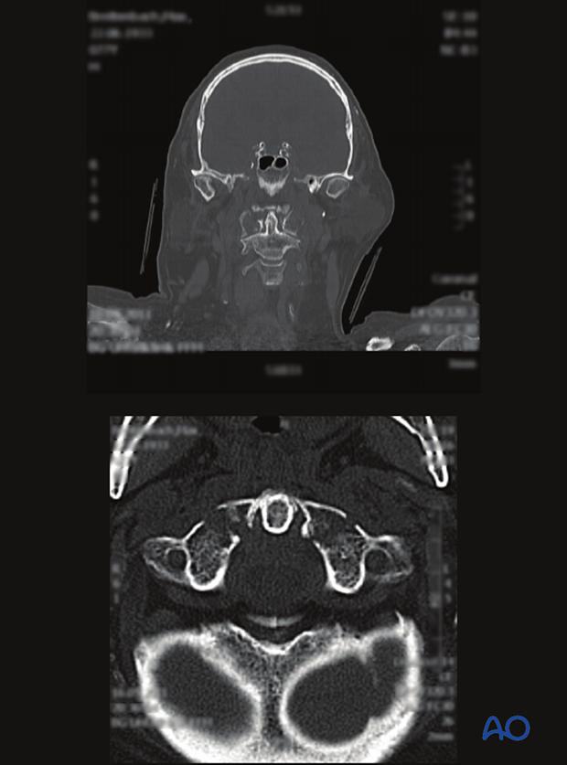
What is seen in this image:
- Odontoid fracture
Which view:
- Sagittal, axial
What this indicates:
- Fracture of the dens axis (odontoid)
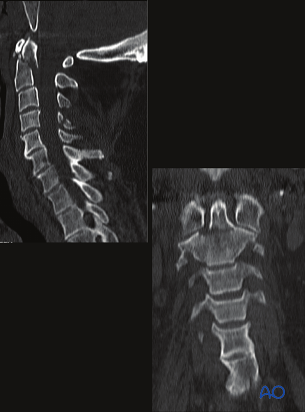
What is seen in this image:
- Traumatic spondylolisthesis of C2
Which view:
- Sagittal, axial
What this indicates:
- Fracture of C2
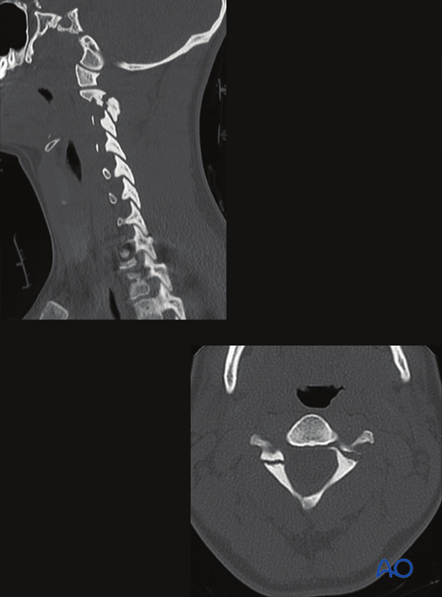
What is seen in this image:
- Prevertebral hematoma and effusion in the C1–C2 joint
- Sagittal reconstruction
What this indicates:
- Occipital condyle dislocation
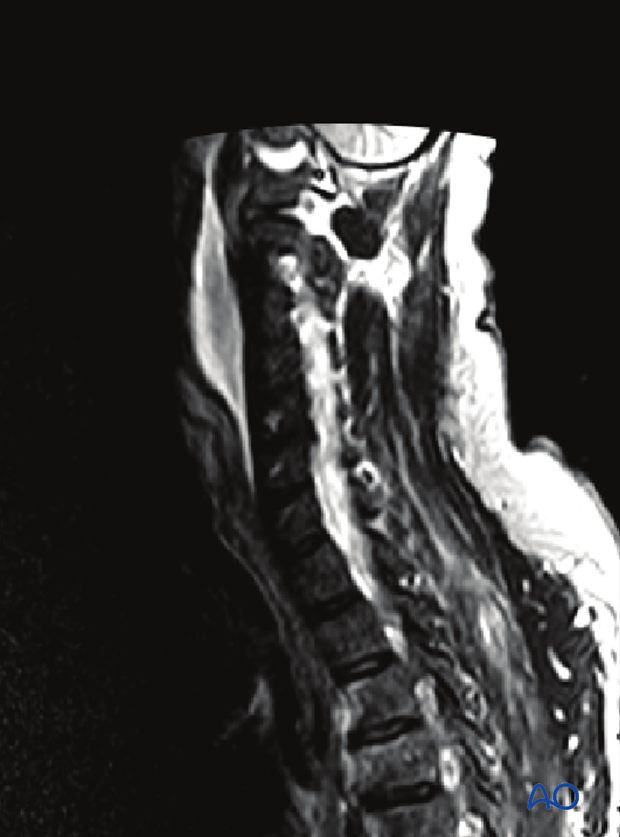
What is seen in this image:
- Hyperintense signal changes in cord
What this indicates:
- Cord injury


