Intraoperative imaging of the distal humerus
1. Introduction
Fluoroscopic visualization of anatomical fracture reduction and correct implant placement for the distal humerus can be greatly facilitated using the following views:
Standard views
- AP view of the distal humerus
- Lateral view of the elbow
Additional views
- Oblique view of the distal humerus
- Axial view of the distal humerus
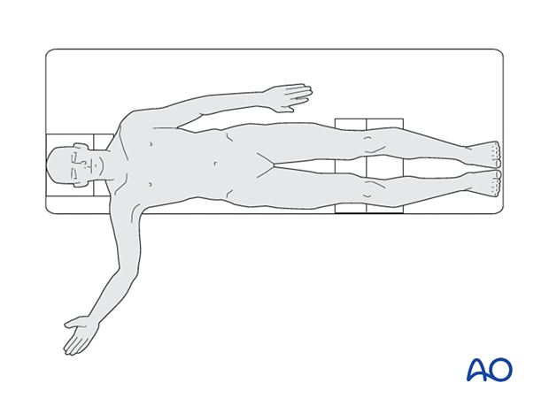
The following represent ideal imaging with the patient placed in the supine position. The posture of the arm and forearm remain the same for patients in lateral decubitus and prone positions.
The orientation of the C-arm has to be adjusted accordingly.
2. AP view of the distal humerus
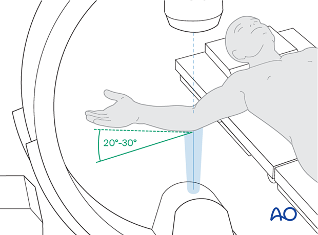
Positioning for optimal view
- Shoulder in 90° abduction and neutral rotation
- The elbow is flexed 20-30°
- The forearm is fully supinated
- The beam is placed perpendicular to the humerus (and in the plane created by the humerus and the forearm)
Verification of optimal view
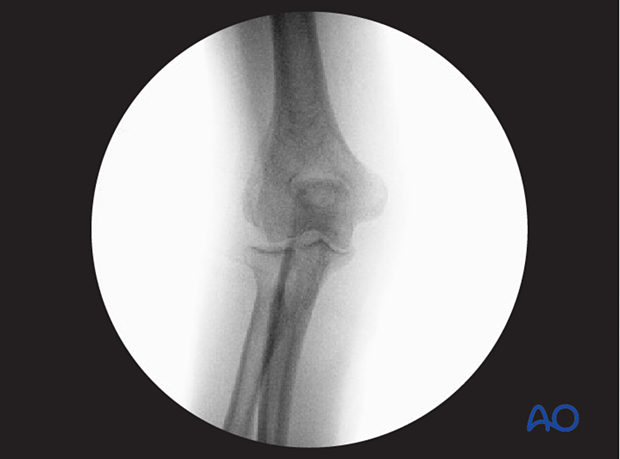
The optimal view is obtained when:
- The optimal outline of medial and lateral epicondyles is demonstrated.
- the tip of the olecranon is centered in the olecranon fossa.
- the anterior and posterior articular margins of the medial trochlear ridge are aligned.
Anatomical landmarks and lines
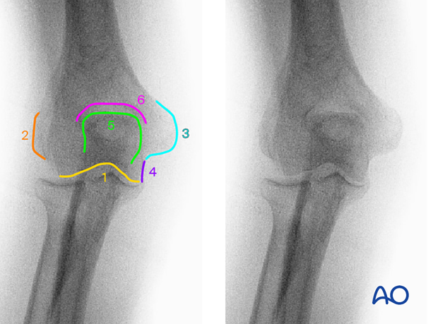
The following lines and landmarks can be observed:
- Distal joint line of humerus
- Lateral epicondyle
- Medial epicondyle
- The medial border of the ulnar trochlea
- Olecranon
- Olecranon fossa
What can be observed
This view is particularly useful to identify:
- Fractures and malaligment of the lateral or medial (epi) condyle, distal joint line, or olecranon
- Implant malpositioning
3. Lateral view of the elbow
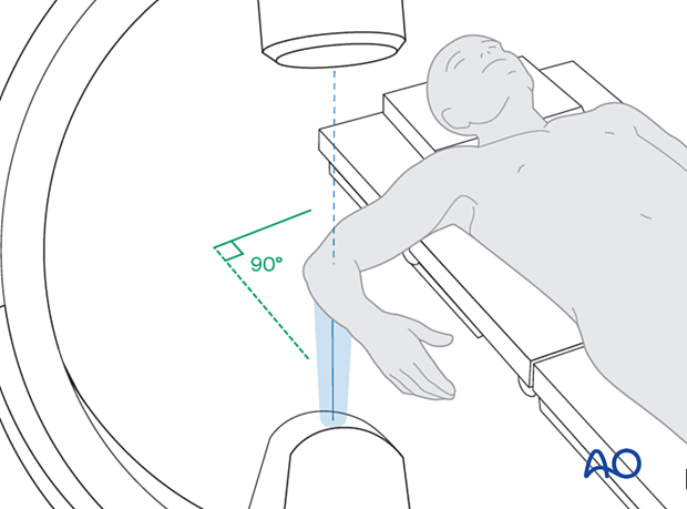
Positioning for optimal view
- The shoulder in 90° abduction and 90° internal or external rotation (in cases with restricted shoulder motion, the beam can be rotated as needed)
- The elbow is flexed 90°
- The forearm is in neutral rotation
- The beam is placed perpendicular to the plane created by the humerus and the forearm
Verification of optimal view
The optimal view is obtained when:
- The ulnohumeral joint is congruent without the "drop sign"
- Radial head and coronoid process are aligned
- The axis of the proximal radial shaft is aligned with the center of the capitellum
- The PUDA is present
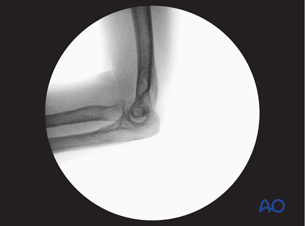
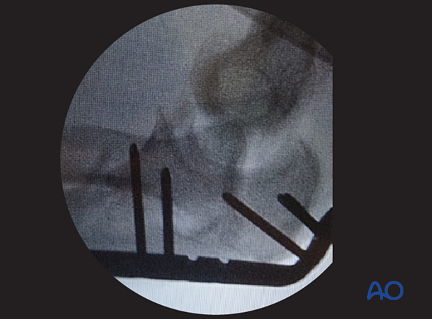
The ‘drop sign’ is the term given to the appearance of an abnormal relationship between the trochlea of the distal humerus and the trochlear notch of the ulna (dotted line) when there is excessive laxity of the capsular soft issues of the ulnohumeral joint, permitting the ulna to ‘drop’ away from the humerus.
In this case a dislocation of the joint has occurred after fixation: the implication of the presence of a ‘drop sign’ is that capsular disruption (including disruption of the named ligaments) remains a problem to be assessed.
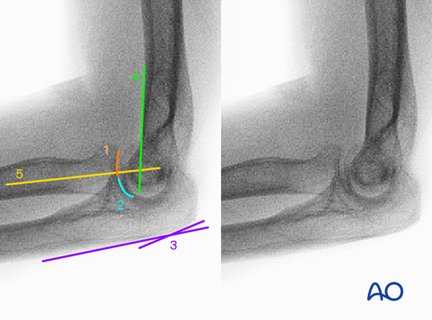
Anatomical landmarks and lines
The following lines and landmarks are seen:
- Joint line of radial head
- Joint line of coronoid process
- Proximal ulnar dorsal angle (PUDA)
- The anterior cortex of humerus bisects the circular projection of the trochlea
- The axis of the proximal radial shaft is aligned with the center of the capitellum
What can be observed
This view is particularly useful to identify:
- Distal humeral fracture malreduction
- Joint laxity with “drop sign” or malalignment of axis of the radial shaft with the capitellum
- Implant malpositioning
4. Oblique view of the distal humerus
Positioning for optimal view
- Shoulder in 90° abduction and 20-30° extension (the beam needs to be 60-70° to the axis of the humerus)
- The humerus is rotated externally 45°
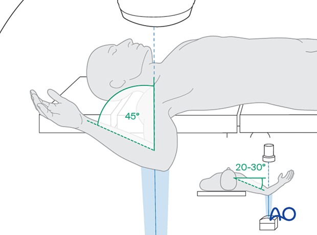
- The elbow is flexed 30-45°
- The forearm is in neutral rotation
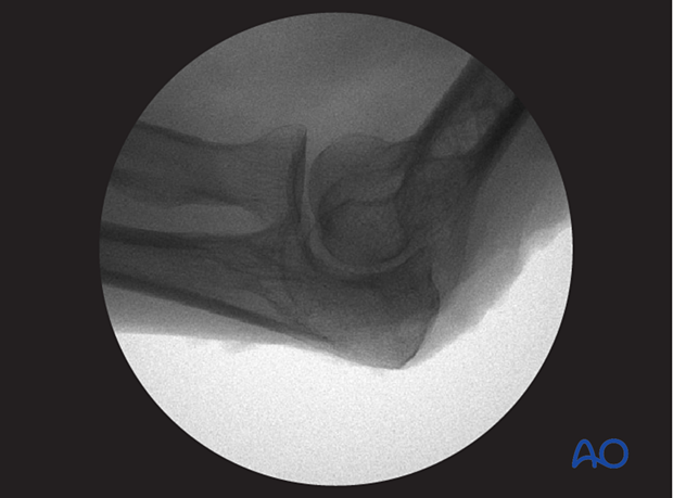
Verification of optimal view
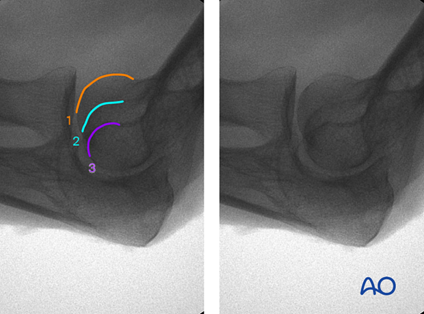
The humerus is rotated externally until the three overlapping circular images of the capitellum and medial and lateral trochlear margins are seen.
Overlap of the ulna and radial head should be avoided.
Anatomical landmarks and lines
The following lines and landmarks can be observed:
- Anterior articular margin of the capitellum
- Lateral margin of trochlea
- Medial margin of trochlea
What can be observed
This view is particularly useful to identify:
- Shear fractures of capitellum and anterior trochlea
- Distal humeral fracture malreduction
- Screw penetration and implant malpositioning
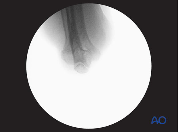
5. Axial view of the distal humerus
Positioning for optimal view
- Shoulder in 90° abduction and neutral roation
- The elbow is flexed as much as possible
- The forearm is in neutral position
- The beam is placed perpendicular to the humerus (and in the plane created by the humerus and the forearm)
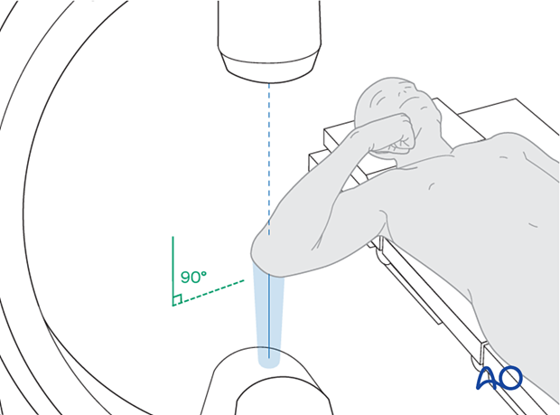
Verification of optimal view
The optimal view is obtained when the:
- elbow is completely flexed
- olecranon tip is centered and congruent with the distal humeral joint line
Anatomical lines and landmarks
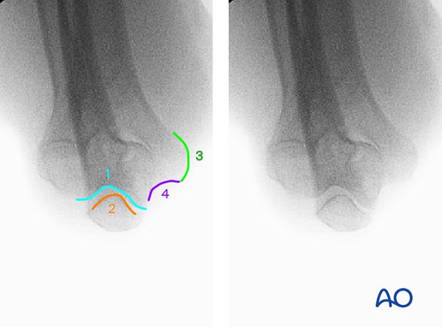
The following lines and landmarks can be observed:
- Posterior trochlear articular margin
- Olecranon tip
- Medial epicondyle
- Bony margin of the cubital tunnel
What can be observed
This view is particularly useful to identify:
- Fractures and malalignment of the olecranon tip and posterior trochlea
- Screw penetration
- Implant malpositioning


