Locking head screw insertion
1. Locking head screws
Introduction
The hole in the plate is threaded, and the head of the locking screw has a corresponding thread.
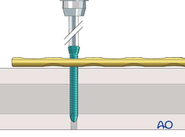
As the screw is tightened, the thread on the head engages with the thread of the plate and locks the screw to the plate at a 90° fixed angle, without compressing the plate against the bone.
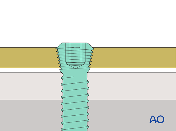
These 3D models show the insertion of a locking head screw (top panel) and a conventional screw in neutral mode (bottom panel).
The conventional screw is inserted in neutral mode and pulls the plate against the bone. Locking head screws engage in the plate using the threads and therefore the plate is not pressed against the bone.
These 3D models allow bending of locking head screws and conventional screws to be simulated.
The fixed angle locking construct (bottom panel) provides considerable stability and there is bending of both the screw and the plate. In contrast, the conventional screw (top panel) can freely rotate in its plate hole without causing deformation.
High stress is shown in red and low stress is shown in green.
Technique
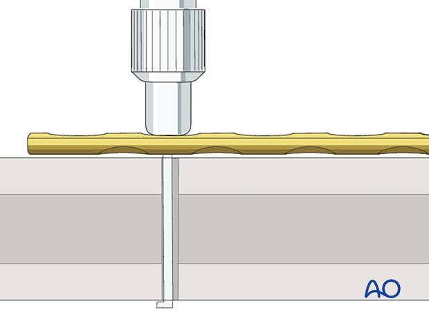
Screw the appropriate drill guide into the plate hole and drill the screw hole.
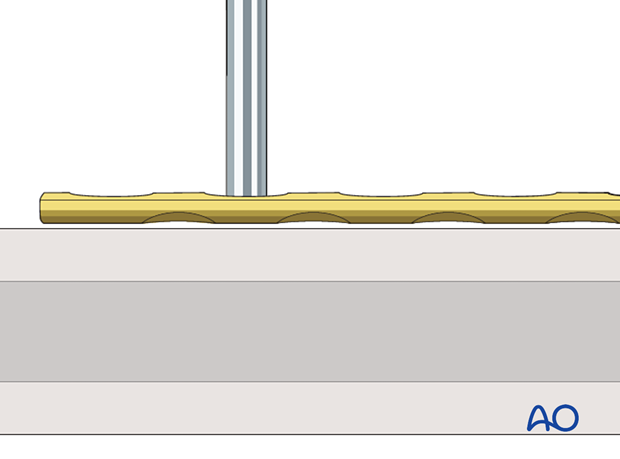
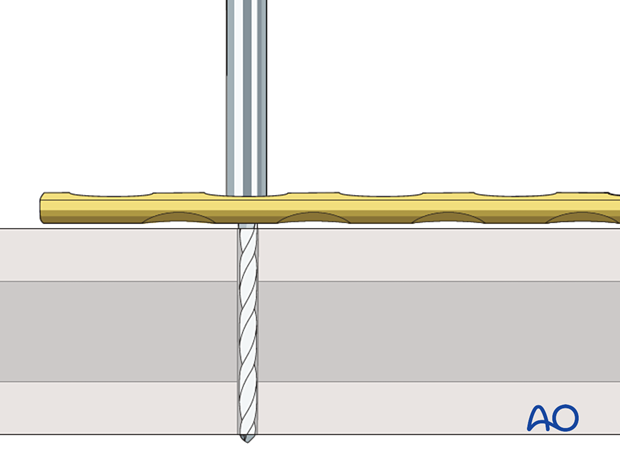
Some systems have calibrated drill bits, so the depth of the tip is indicated. As the tip of the drill bit penetrates the far cortex, the depth can be measured from the shaft of the drill bit.
The depth of the hole will depend on whether monocortical or bicortical screws are used.
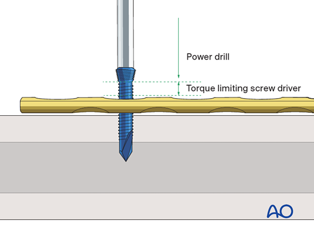
No sleeve is used if self-tapping, self-drilling screws are used. These should only be used as unicortical screws. If the screw is used to drill a hole in the far cortex, it only advances slowly as it is turned, and the threads in the near cortex may be stripped.
Unless a calibrated drill bit is used, a depth gauge is used to determine the screw length.
The screw is inserted and tightened with a torque-limiting screwdriver. As the screw is tightened, it is locked to the plate.
Self-drilling screws
This 3D model shows different types of screw tips.
Self-drilling screws (right) can be inserted in the bone without preparation. Self-tapping screws (middle) need pre-drilling of a pilot hole but can create their own threads by means of cutting flutes at the tip. Standard, round-tipped screws (left) need pre-drilling and tapping.
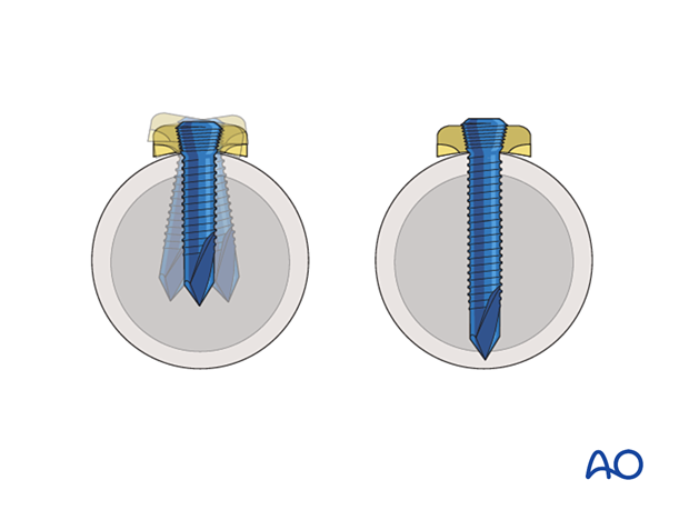
If the near cortex is thick, there is no tendency for the screw to move within the bone. If the near cortex is thin, there may be a tendency for the screw to move. This may be minimized by inserting the tip of the screw into or past the far cortex. This requires an accurate judgment of the screw length as the screw tip is sharp and can injure soft tissue if it protrudes too far past the far cortex.
Under torsional load, a bicortical screw provides the most stability, even in osteoporotic bone (top panel). Bone quality is an integral part of the construct: this becomes evident when comparing a monocortical screw in osteoporotic bone (middle panel) and a monocortical screw in normal bone (bottom panel) under torsional load.
High stress is shown in red and low stress is shown in green.
2. Variable angle locking head screws
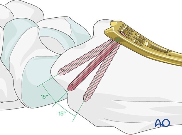
When polyaxial screws are used, the design of the plate hole allows for the screw to be inserted in various angles up to 15° and still provide angular stability due to a special threaded screw head and plate interface.
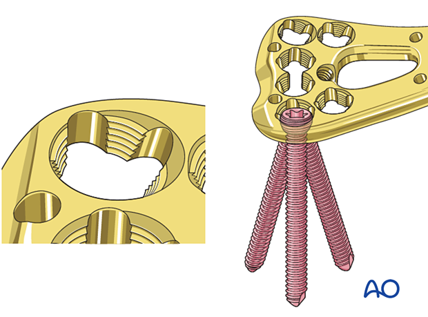
Variable angle locking head screws must be placed with high precision. Use the appropriate drill guide to prepare the screw hole. This may be a guide that fixes the screw in the nominal axis (central or 0° off axis), or at an angle up to 15° off the nominal axis.
Some systems have calibrated drill bits, so the depth of the tip is indicated. As the tip of the drill bit penetrates the far cortex, the depth can be measured from the shaft of the drill bit.
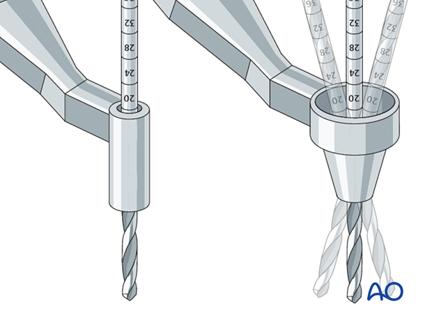
Generally, the closer the screw is inserted to the nominal axis, the more angular stability there will be.
The depth of the hole will depend on whether monocortical or bicortical screws are used.
Screw insertion is analogous to the procedure described above.
